Introduction
This document contains instructions for how to use an 8 bit EPROM programmer to program 16 bit EPROMs. While this is written for the Amiga the instructions should work for all 16 bit EPROM applications, e.g. Atari ST, Sega Megadrive.
For those interested, here is some Background Reading about how ROMs fit into a computer's memory and why this works.
Who this is for
This is for people who already own an 8 bit programmer and wish to program 16 bit roms. If you do not own an EPROM programmer and are looking to buy one it is easier to spend the extra $50 on a 16 bit programmer to begin with.
Equipment required
-
An 8 bit EPROM programmer that can program the 27C040 EPROM, e.g. Genius G540
-
A 16 bit EPROM, either 27C400 or 27C800
-
A suitable computer to control the programmer. If using the Genius G540 I suggest using a Windows XP box.
-
Electronics components on the bill of materials below.
-
Python3
-
A ROM image to program
-
This zip file, containing these instructions, the background reading, schematics, various EPROM datasheets, and a python scripts. You must be logged in to download it.
Disclaimer
While every effort has been made to ensure the accuracy of this article I cannot guarantee it is error free. This project involves making an electronic circuit and a certain amount of skill is required to complete it. The author and Amiga Retro Brisbane and its members take no responsibility if you build it and you break EPROMs, your EPROM programmer, your Amiga, or anything else. Do not contact ARB members for Kickstart images; these may be purchased legally from Colanto or Hyperion.
License
This document is derived from an earlier document by the same author, released in the public domain, and remains copyright (c) Gary Lindsay, 2018 and 2022. It may be distributed far and wide provided it is distributed in its entirety including this message. It may not be included in a publication sold for a fee without written permission from the author. If you improve the design (e.g. by designing a PCB) please supply a copy to the author.
General
Some prior experience doing electronics projects and knowing how to solder is highly beneficial. If you wish to make a permanent solution you need to solder a circuit on a prototype board PCB. A basic understanding of the internal workings of computers is also beneficial but not mandatory, as is a knowledge of some basic mathematics. While some background reading is provided a certain level of technical knowledge of electronics and computers is assumed. It is not complicated but it is not suitable as a first project either.
While the instructions in this document should work for any 8 bit programmer, they are only tested with the Genius G540 programmer from Shenzhen Stager Electronic Co. Ltd. This was a cheap 8 bit programmer bought from eBay a few years ago and is a really good piece of kit for the price, provided you aren't worried about grammatically correct documentation ;-). Note that if you want to install the driver on recent versions of MS Windows you must temporarily allow unsigned drivers during installation. I suggest running the programmer on an XP box if you still have one.
The Adapter
Bill of Materials
U1: 42 pin IC socket
S1: 8PDT switch1
P1: Plug for programmer2
Hook-up wire3
R1-R17: Pull-up resistors4
Prototype Board
1An actual 8PDT switch is not strictly necessary. My adapter uses jumpers that the user changes each time. You could also use DIP switches, jumper wires, whatever is at hand.
2Some sort of plug to connect the adapter to the programmer is required. My one uses slightly modified header pins, extending below the PCB rather than above it, connected to a little board below the adapter board which in turn had another set of header pins. I suggest getting pins as long as you can find; I used 20 mm pins but they are a bit too short. There is a photograph in the construction section.
3It is highly recommended that each type of line (control lines, data lines, address lines) use a different colour, and that the GND line is black, the VCC line is red, and the VPP line is yellow. I used cut-up CAT5 network cable for all lines except the power lines using blue for address lines A0-A8, white-blue for A9-18, green for data lines O0-O7, white-green for O8-O15, and brown for the control lines.
4Pull-up resistors, suggested value between 10 K ohm to 20 K ohm (close enough is good enough, but too low and they will use too much power and too high and they won't work). They do not all have to be the same value, just use whatever is at hand.
Schematics and circuit description
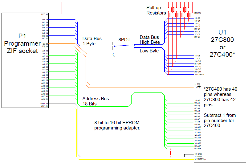
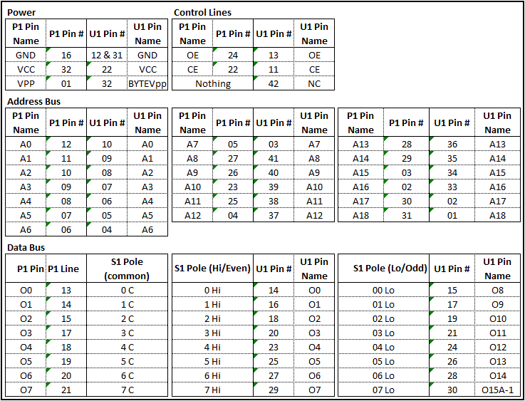
Consider P1 as if it were a 27C040. The address lines are connected like-for-like, i.e. A0-A0, A1-A1, etc, as are the control lines CE and OE, and the power lines VCC, VPP, & GND. The data lines O0-O7 from P1 are connected to the centre of each pole of the switch (or into the central jumper), with the high byte of U1 (O0-O7) being connected to one side and the low/offset byte (O8-O15) to the other side. A table is provided below:
Construction
Construction is fairly straightforward. Put the IC socket (U1) on one side of the prototype board and whatever you're using as P1 on the other side. Take care with geometry of the board that the edge of the board doesn't cover the programmer's ZIF socket otherwise it makes it difficult (not impossible) to use. Then install S1; I used three rows of eight header pins above P1.
Next install a resistor between A18 and GND (pins 1 and 12 on U1) flush to the board, and install pull up resistors between each of the data lines and the VCC line.
Now use wires and solder bridge to connect the various address, power, and control lines between P1 and U1, and between P1, S1, and U1 for the data lines.
Alternatively you could design a PCB and get it made up by JLCPCB or similar, it will be significantly easier than using a prototype board.
Photographs
Top of completed adapter:
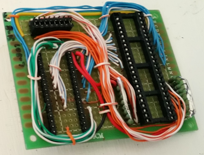
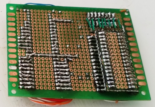
Bottom side of the adapter. note the sub-board, this is the solution I used for P1 with 20 mm header pins (what I had on hand at the time). It would be significantly easier to use 35 mm pins:
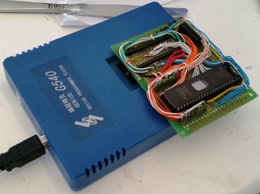
Adapter on the Genius G540 programmer:
Burning a ROM
Set up the ROM images
To use the adapter we need to burn the hi (even) byte to data lines 0 to 7 and the lo (odd/offset) byte to data lines 8 to 15 in two separate operations. In order to do this we need image files of the hi and lo bytes separately.
First copy the ROM image(s) to a directory and extract the zip file in the same directory.
Decrypt ROM image
If the ROM image files are encrypted with a key file (i.e. they were purchased from Colanto) delete the extra 11 bytes at the start of the rom saying "AMIROMTYPE1" to make it is exactly 524288 (80000h) bytes long (262144=40000h for 256k roms). Then decrypt it with the command:python xor.py EncryptedRomFile KeyFile DecryptedRomFile
A decrypted ROM file will now be present. You can check it by opening in your favourite hex editor or text editor, you should see a version and a copyright notice from Commodore in the first few lines (this is the start of the exec.library):

Concatenate KS 1.x ROM images
Kickstart 1.x ROM images are only 256 kb but the compatible 27C400 EPROMs are 512 kb. In order to make the ROM image fill the entire 512 kb EPROM we concatenate the ROM image onto itself, which will have the effect of writing it to the EPROM twice to fill the entire 512 kb. Check the file size first.
In Windows use the copy binary function, on the Windows command line:
copy /b kick13.rom+kick13.rom 1.3_cat.rom
On Debian flavoured Linux (including Raspbian) use cat:
cat kick13.rom kick13.rom > 13_cat.rom
Concatenate for switching dual kickstart
It is possible to make a switching dual kickstart using the 27C800 (more about this below). This is useful for users who use OS 3.1 or greater for a hard disk system but still want to boot older games from floppy or Gotek. In this example Kickstart 1.3 will be at the start of the EPROM and Kickstart 3.1 in the second half, beginning at offset 0x040000. Note that we will concatenate the 1.3 ROM twice as per above (1.3 will be at 0x000000 and offset at 0x020000).
In Windows use the copy /b function, on the Windows command line:
copy /b kick13.rom+kick13.rom+3.1a500.rom 13_31.rom
On Debian flavoured Linux use cat:
cat kick13.rom kick13.rom 3.1a500.rom > 13_31.rom
Byteswap and split the ROM image
This step is supposed to be possible by loading the first of two (odd) and second of two (even) bytes into the buffer of the software that comes with the programmer but it never seems to turn out with the G540's software and it was easier to write a python script than figure out why.
A ROM image for the Amiga must be byteswapped to account for the machine's Big-Endianness (swap byte 1 with byte 0, byte 3 with byte 2, byte 5 with byte 4, and so on, see the background reading). If using a 16 bit EPROM programmer that would be done, but in this case the even and odd bytes will be burned independently so it is not necessary.
Split the ROM image into even/hi and odd/lo bytes using the python script splitter.py:
python splitter.py 13_31.rom
There should now be two files called 13_31.rom0.bin and 13_31.rom1.bin. The 0.bin file is for the even/hi byte, and the 1.bin file is for the odd/lo byte.
The even byte (0 file) will start with the second byte of the source file:

The odd/offset byte starts with the first byte of the source file:

Be aware, Diagrom comes pre-byteswapped so the two files created by the splitter script will be named incorrectly (DiagROM is a powerful troubleshooting tool for the Amiga and may be the subject of a future article). Also note that ROMs intended for little-endian machines will also have incorrectly named files.
Programming
Plug the programmer into the computer without the adapter and start the EPROM programming software. Choose device 27C040 but make sure the voltages are correct, some vendors use different voltages for VCC and VPP. Try Atmel or AMD.
Load the file for the hi byte (13_31.rom0.bin) into the software's data buffer. If you are programming a single kickstart onto a 27C400 make sure you select to fill the blank area with FF (all 1s - so that the second pass does not actually program anything). Scroll down to addresss 0x040000 and make sure all the bytes after this address are FF.
If programming the dual kickstart on a 27C800 make sure byte 1 (NOT byte 0) from the second ROM image is at address 0x040000.
Put the blank EPROM into the adapter. If you are burning a 27C400 make sure that pin 1 on the IC goes into the place for pin 2 on U1 (leave U1 pins 1 and 42 empty), same as if installing it in an Amiga. Set S1 to program the hi byte (data lines 0-7). Put the adapter into the programmer and program the EPROM as normal.
If programming a 27C400 the verification should fail at address 0x040000 (exactly half way) because there will be data where the software is expecting FF; don't worry, this is normal.
When the hi byte is done change S1 to the lo byte (data lines 8-16) and repeat the process using lo byte file. If everything has gone well you should be able to put the EPROM into your computer and it will boot. It won't break your computer if you make a mistake, but it will black screen.
Dual Kickstart EPROM
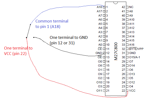
A switch is required for the dual kickstart. Simply solder a wire to pin 1 on the 27C800 (A18) and connect the other end to the middle terminal of a DPST switch. Connect one side of the switch to a convenient GND (pin 12 or 31 will be fine, or something else on the motherboard), and the other side of the switch to VCC (pin 22). Put the switch somewhere convenient, in the old days this used to be a hole in the case under the disk drive.
 Total Members: 170
 Latest: psyolent
 Total Posts: 1872
 Total Topics: 438
 Online Today: 87
 Online Ever: 262
 Users: 0
 Guests: 72
 Total: 72

 DARE TO DREAM - A new boo...
by Marcio D.
  First release of SMD2000 ...
by psyolent
  July 2024 - Gem'X
by joey
  July-August 2024 - Sim Ci...
by joey
  ONLINE EVENT (short notic...
by Marcio D.
  Amiga Retro Brisbane Proj...
by Gazzmaniac
 June 2024 - John Madden F... by NinjaKat
June 2024 - Putty Squad by NinjaKat
 Blingboard64 - New keyboa...
by Marcio D.
 Modern 8bit computers - n... by intangybles


